Standard
PRO-CAST® Construction
Caster/Coater Construction
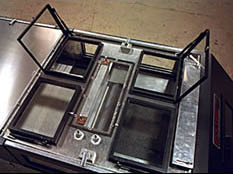
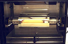
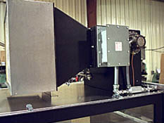
The drying chamber, or conveyor housing, is approximately 20″ (500mm) wide by 12″ high (300mm) and is composed of individual welded sections of heavy gauge aluminum that are joined together to form a continuous enclosure.
The chamber is thermally insulated and equipped with tempered glass view ports positioned on hinged panels, allowing viewing of the casting process and access into the chamber for maintenance. Aluminum tooling plates form the chamber floor, which is supported on a structural steel frame. The frame consists of welded modular sections that are joined to form an integral structure which incorporates leveling pads and removable aluminum side access panels.
Conveyor/Carrier
The tape caster incorporates a web handling system designed for up to 14″ (355mm) wide polymer carrier, which is to be provided by the Purchaser.
Carrier Conveyor Drive
A variable speed drive, employing a digital feedback speed sensor, located at the discharge end of the tape caster/coater conveyor drive, is provided complete with a digital operator interface mounted in the control panel. Carrier unwind and rewind spool shafts, are easily removable from quick action, locking pivot collar safety chucks provided at the casting/coating and discharge ends of the caster. Bladder type air core chucks will be provided.
Carrier Alignment & Tension Control System
An electro-mechanical steering unit , and automatic centering sensors, actuators, and power unit are provided at the exit end. These assure +1/16″ positive location of the carrier film on the take-up spool.
A pneumatic brake (or equal), will be provided at the entrance end. This system maintains a preselected constant tension of the web and product.
Casting Surface
A granite block with a +0.0003″ (or better) tolerance precision ground casting surface, is securely mounted in a height adjustable support fixture at the entrance end of the tape caster. The granite block fixture will allow for containment of slurry in the event of uncontrolled delivery. An anti-static tinsel bar is located on the caster frame just before the granite block.
Feed End
A suitable enclosure for the entrance end will be provided to contain the casting/coating vapors and maintain a clean atmosphere. Access to the casting/coating head will be through a window, with loading and unloading of film through an access door.
Doctor Blade
An adjustable single doctor blade fixture with a micrometer adjustable lift of (0″ to 0.250″) is provided for control of tape lay-down thickness.
NFPA & NEC Standards
This tape caster/coater will be built to meet applicable NFPA 86 and NEC standards in effect at the time this proposal is submitted. The complete atmosphere and electrical systems have been designed to meet all significant and well-defined standards that are recognized in the United States.
Drying Chamber & Interlocks
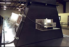
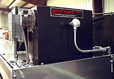
The drying chamber will consist of a variable speed, atmosphere intake blower, with filtered intake duct complete with atmosphere flow interlock, pressure transmitter, solvent sensor, temperature control and over-temperature protection, if applicable. The filtered atmosphere will provide counter-flow atmosphere between the exit end and the exhaust at the entrance end.
The intake blower, mounted on vibration isolation dampers, is positioned near the entrance end of the drying chamber for efficient counter-flow removal of casting vapors.
The air inlet duct is provided with an air pressure switch interlocked to the control system such that sufficient fresh air is introduced into the drying chamber to remove any residual solvents during the purging cycle. An initial purge of the drying chamber is required prior to operation of the heating, conveyor, and slurry delivery systems. If casting with flammable solvents, a high limit solvent sensor is provided and is interlocked with the control system such that solvent vapor levels exceeding 50% will initiate a casting shutdown sequence.
Exhaust stack ducts and connections to the discharge side of exhaust fan are Purchaser provisions.
Control Console
Control instrumentation, switches, function labels, status lights, relays and fuses are mounted in a control console attached to the caster structure. The equipment is ready for Purchaser connection to the required electric service of 240V/3Ph/60Hz (or as required) at the main disconnect, which is to be provided by the Purchaser.


